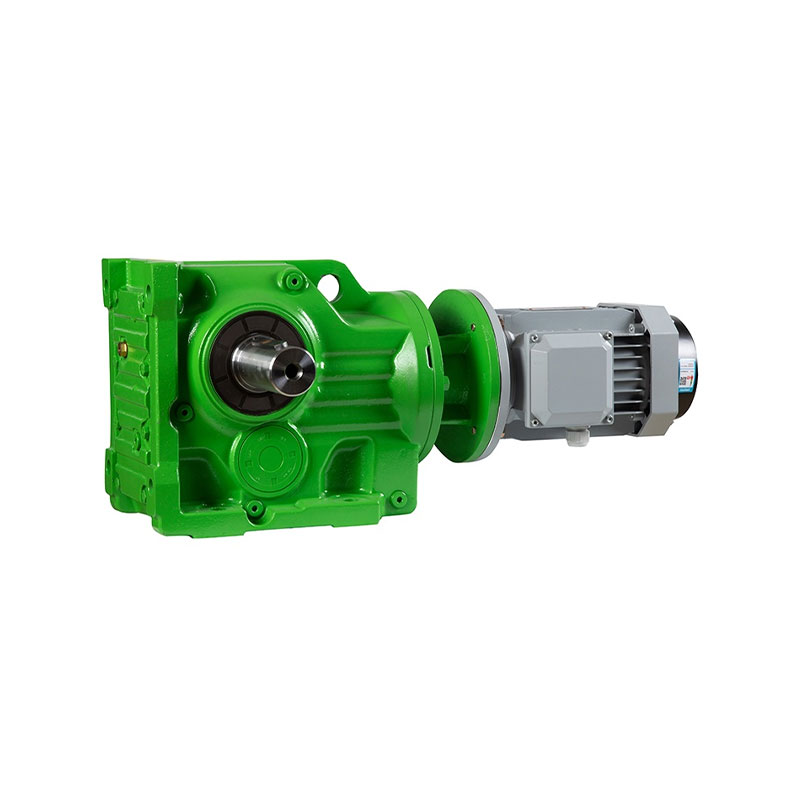
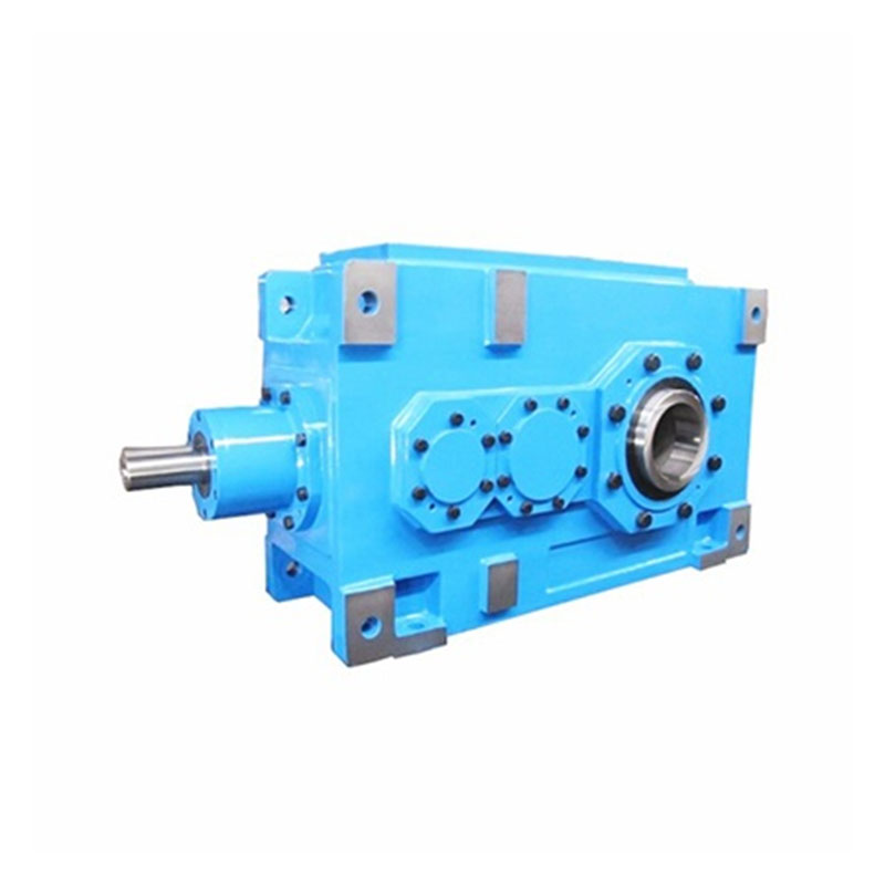
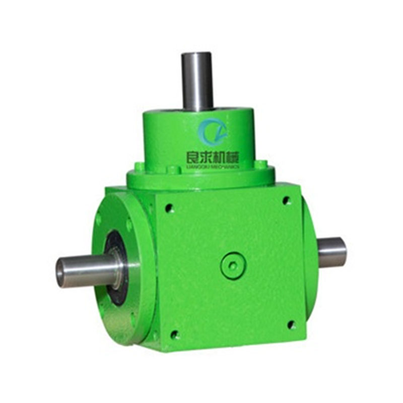
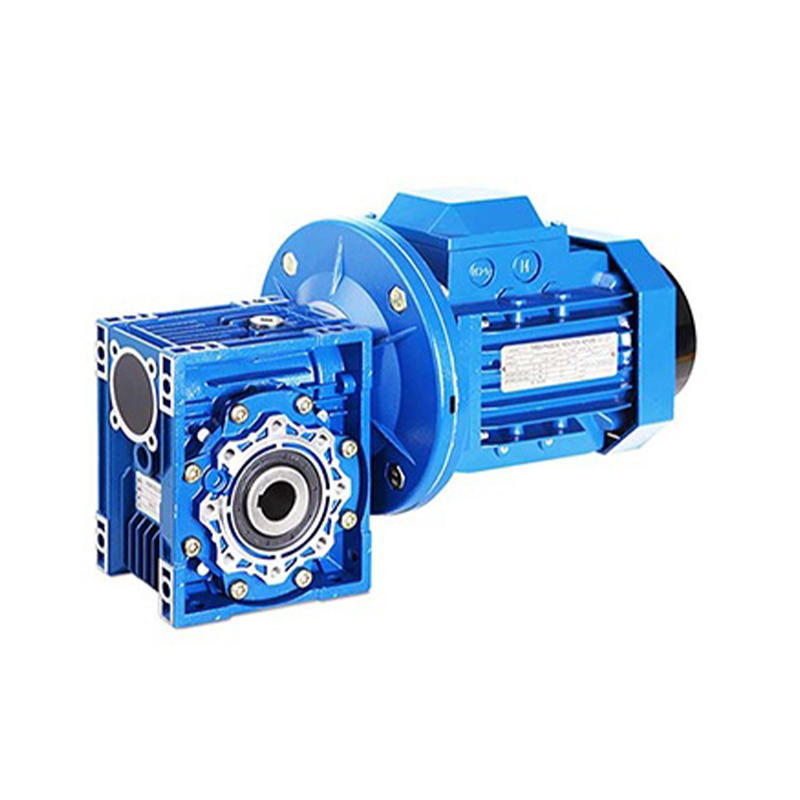
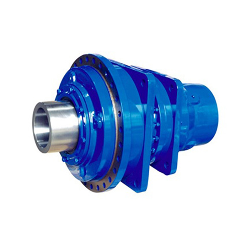
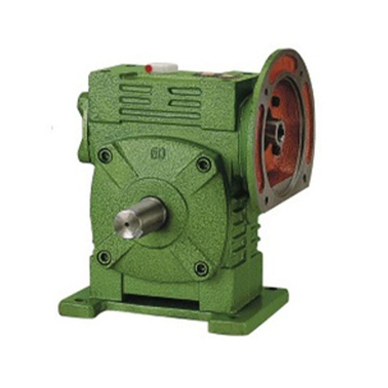
The WP worm gear reducer is developed based on the WD reducer. The worm is made from 45# high-quality steel through heat treatment, and the worm wheel is cast from tin bronze, offering good wear resistance, especially in terms of load-bearing capacity. It is mainly used for speed reduction in various mechanical equipment such as plastic, metallurgy, beverages, mining, lifting and transportation, chemical engineering, and construction.
Features:
1. It can achieve a large transmission ratio with single-stage reduction, with a compact structure. Most models of this reducer have good self-locking ability, which can save the braking device in mechanical equipment that requires braking.
2. The meshing friction loss between the worm thread and the worm wheel tooth surface is large, so the transmission efficiency is lower than that of gears, and it is prone to heating with higher temperatures.
3. The reducer has higher requirements for lubrication and cooling.
4. Good compatibility: both the worm and worm wheel are manufactured according to national standards, and standard components such as bearings and oil seals are used.
5. The housing is available in two types: a basic type (with a baseplate and either vertical or horizontal structure) and a universal type (rectangular housing with multiple fixed screw holes, without baseplate or with additional baseplate options).
6. The input shaft connection method has the basic type (single input shaft or dual input shaft) and the motor flange type.
7. The direction of the output and input shafts includes input shaft up or down, output shaft up or down, and input shaft up or down.
8. Two or three reducers can be combined to form a multi-stage reducer to achieve an extremely large transmission ratio.
Working Conditions:
1. The worm speed of the worm gear reducer should not exceed 1500 r/min.
2. The operating temperature range is -40℃ to +40℃. When the working environment temperature is below 0℃, the lubricating oil must be heated to above 0℃ before starting. When the working environment temperature exceeds 40℃, cooling measures must be taken.
3. The worm gear reducer’s input shaft can rotate in both forward and reverse directions.
Precautions:
1. The worm shaft must never be used as the input shaft.
2. The matching motor (i.e., the power) must not exceed the value specified on the nameplate.
3. If the user wants to change the direction of the input shaft, the end caps of both ends of the shaft can be removed, the worm shaft can be taken out, adjusted by 180°, and reinstalled. When assembling, do not strike it forcibly; slowly rotate both shafts to allow them to mesh.


 英文
英文